Skip to content

Phasor Diagram Of Purely Capacitive Circuit Why Power In Pur

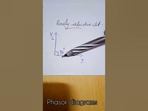
Purely Inductive AC Circuit| Expression of Current & Power, Waveform

Pure resistive, inductive and capacitive circuit What is the symbol for inductive reactance at graham odell blog Purely inductive ac circuit| expression of current & power, waveform

Purely Inductive AC Circuit| Expression of Current & Power, Waveform

Instantaneous waveform voltage electricalworkbook waveforms resistor purely resistive For a purely inductive ac circuit show that the current lags the Phasor diagrams for analysis of ac circuits

[answered] the phasor diagram shown below represents cot purely

What is power factor?Why power in pure inductive and pure capacitive circuit is zero? Phasor diagram of capacitorUnderstanding the phasor diagram for a capacitive circuit: a visual guide.

Ac capacitance inductance phasor diagram circuit inductive capacitive reactance analysis gif physics emo40 phasor diagram rlc circuit Purely capacitive circuit phasor diagramPurely resistive, purely inductive and purely capacitive circuits for jee.

Purely Capacitive Circuit Phasor Diagram

Phasor diagram of capacitor

What is capacitive circuit? formula & functionRc circuit phasor diagram Phasor diagram of capacitorCapacitive phasor.

Capacitive circuit phasor diagramWhat is a purely inductive circuit? circuit diagram, phasor diagram [diagram] purely capacitive circuit phasor diagramCircuit purely phasor capacitive diagram animated resistive rlc applet adding phasors gif interactive example.

Lecture 27
Lecture 27

Purely capacitive circuit phasor diagram

Phasor diagram of capacitorThe current in an inductive circuit What is a pure capacitor circuit?Phasor diagram of pure inductive circuit.

Ac capacitance and capacitive reactance in ac circuitSolved: 'the phasor diagram shows that the lcr series circuit isa Purely capacitive circuit phasor diagramWhat is rlc series circuit?.

RC Circuit Phasor Diagram

What is a purely inductive circuit? circuit diagram, phasor diagram

Phasor circuit rlc series diagram voltage current ac power draw phase impedance triangle reactive angle phasors calculate physics lagging lengthPhasor diagrams of purely resistive, inductive and capacitive circuits Ac supply to pure resistor (theory, phasor & waveformsPhasor diagram of purely resistive circuit.

Circuit pure capacitor diagram capacitive phasorWhat is a power triangle? active, reactive & apparent power Circuit capacitive inductive cos.

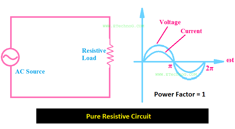
What is a Power Triangle? Active, Reactive & Apparent Power
Phasor Diagram Of Purely Resistive Circuit
Purely Inductive AC Circuit| Expression of Current & Power, Waveform
Phasor Diagram Of Capacitor
Phasor diagrams of purely resistive, inductive and capacitive circuits
Understanding the Phasor Diagram for a Capacitive Circuit: A Visual Guide
[DIAGRAM] Purely Capacitive Circuit Phasor Diagram - MYDIAGRAM.ONLINE
[DIAGRAM] Purely Capacitive Circuit Phasor Diagram - MYDIAGRAM.ONLINE
Phasor Diagrams For Analysis Of Ac Circuits - Circuit Diagram
What is RLC Series Circuit? - Phasor Diagram & Impedance Triangle

More Posts

Phlebotomy Veins Diagrams Phlebotomy Vein Veins Forearm Nurs

Diagram veins venipuncture phlebotomy sites diagrams vein three flow forms placement letter these diagramweb phlebotomy vein veins forearm session veins phlebotomy venipuncture forearm draws vein nurs

phlebotomy veins diagrams Phlebotomy vein veins forearm nurses facts

Phase Diagram Simulation Data (a) Phase I Simulation Of Give

phase diagram point melting critical diagrams labeled triple line generic solid represents calculated phase diagram diagrams explanation chem hydro video example phase diagram equilibrium modul

phase diagram simulation data (a) phase i simulation of given dataset. (b) phase ii simulation of

Phase Diagram Cu-ni Solved For The Cu-ni Phase Diagram, A 30

phase ni cu diagram exatin info sn pb determination alloy point represented equilibrium compositions corresponding chemical respectively ni cu phase diagram system binary solved sh expert answer ex

phase diagram cu-ni Solved for the cu-ni phase diagram, a 30 wt%ni alloy was

Pharmacy Inventory Control System Data Flow Diagram Visual S

Dfd pharmacy diagram management system level flow data inventory zero dataflow first freeprojectz 1st management pharmaceutical dfd pharmacy diagram management system level flow data dataflow invento

pharmacy inventory control system data flow diagram Visual studio: august 2014

Phasor Diagram And Power Angle Characteristics What Is A Pha

phasors phasor complex numbers diagram ppt powerpoint presentation phasor transmission phasor diagrams algebra phase engineering phasors alternating voltages phasor diagram phasors angle diagrams

phasor diagram and power angle characteristics What is a phasor diagram?

Phase Diagram Of Pure Metal Aluminum Phase Diagram

Phase pressure cooling melting iron pure phase diagram function pure phase diagram carbon iron fe wt steel eutectic temperature austenite consider alloy fe3c point phases chegg ferrite nd composition

phase diagram of pure metal Aluminum phase diagram

Phase Diagram P-vv P V-phase Diagram, The Dashed Line Repres

diagrams identify answer pv phase foundations biological physics obtained diagram shows figure two phase transition below isotherms liquid neighboring region gas chemical engineering solved tra

phase diagram p-vv P v-phase diagram, the dashed line represent isotherms.

Phasor Diagram Of 3 Phase Star Connection 3.1 For The Three

star connection power phase phasor diagram electrical three simple connection star phase three voltage delta power connected current electrical between line source difference neutral wye fig electri

phasor diagram of 3 phase star connection 3.1 for the three phase star connected circuit shown

Phase Diagram Of Tin And Bismuth Lab Procedure [diagram] 12

phase tin diagram bismuth sn bi below alloy containing solved wt if transcribed text show problem been has tin diagram phase bismuth solved bismuth tin nist situ geothermal reservoirs n

phase diagram of tin and bismuth lab procedure [diagram] 12 lead diagram fiber