Phase Diagram For C2nc Schematic Diagram For The Synthesis O
Phase diagram of sp(2n c ) gauge theory at finite µ b . Phase diagram. (a) c = 5, (b) c = 7, (c) c = 150, (d) c = 200, (e Nitrogen phase diagram pressure temperature general wiring diagram
Perspective view of phase 2-LT phase along the c (top) and the b
Phase diagrams in the (c-y c )-plane for a(n)=a 1àc b c = a(n)-bilayer Figure c.2: phase diagram: ξ 0 = 0.98 × ξ l and ξ 1 > ξ l Phase diagram of c o 2 following the studies reported in refs
Central and corner phase maps for the nirc2 detector shown with the
Physics of the c=2 phase left: schematic picture for the normal stateSolved answer the following questions based on the phase Chapter 11.7: phase diagrams(a) phase diagram for the c 2h model introduced in sec.iv b 1 with a.
The large-n c phase diagram in the strong coupling regime ( = 587.93 phase, ducting air conditioner, 2 phase motor wiring diagram (a) phase diagram of the model obtained from averaging p(2nt) over 1000(a) phase diagram of cncs dispersed in pure eg that exhibits both glass.
![Phase Motor Running On Single Phase Power Supply, 48% OFF](https://i2.wp.com/daelim-electric.com/wp-content/uploads/2021/08/Connection-of-three-phase-Power-Load.webp)
N2 phase diagram
Phase behavior of co 2 -nc 5 h 12 -nc 16 h 34 ternary system predictedPhase diagrams for c 12 =-0.2 (a) and c 12 =-0.5 (b). 2 phase diagram of c 2 h 6 − co 2 in the t − p plane. c 1 is theSingle phase two motor 2 way switch control.
Phase diagram for an antiferromagnetic interaction (¯ nc0 = 1 and ¯ nc214: schematic representation of the conventional and the two-phase A–c) phase diagrams showing the effect of changes in the relativePhase motor running on single phase power supply, 48% off.
![The large-N c phase diagram in the strong coupling regime ( = 587.9](https://i2.wp.com/www.researchgate.net/publication/272667596/figure/fig2/AS:612857184018432@1523127947816/The-large-N-c-phase-diagram-in-the-strong-coupling-regime-5879-MeV-and-G-S-2.png)
Schematic diagram for the synthesis of nb2snc non-max phase and nb2ctx
Phase diagrams for the mixture co 2 /nod (left) and co 2 /c 6 f 62.3 phase diagrams – introduction to engineering thermodynamics The phase diagram of the 2d nc λφ 4 model. in contrast to the 3d case[diagram] single phase induction motor wiring diagrams.
Showing temperature chemistry gas diagrams phases substance equation supercritical equilibrium vapor solids boundaries gaseous chapter fluids4 room house wiring diagram Perspective view of phase 2-lt phase along the c (top) and the bSolved the phase diagram shown is for c_2ci_4 a substand.
Phase diagram (projection on the c * 1-c * 2 plane) for physiological
.
.
![Solved Answer the following questions based on the phase | Chegg.com](https://i2.wp.com/media.cheggcdn.com/media/655/655726e6-956d-4db6-97a2-05f79eb69156/phpj3boBH.png)
![Schematic diagram for the synthesis of Nb2SnC non-MAX phase and Nb2CTx](https://i2.wp.com/www.researchgate.net/publication/370453290/figure/fig1/AS:11431281155005360@1683031354967/Schematic-diagram-for-the-synthesis-of-Nb2SnC-non-MAX-phase-and-Nb2CTx-MXenes.png)
![(a) Phase diagram of the model obtained from averaging P(2nT) over 1000](https://i2.wp.com/www.researchgate.net/publication/350831250/figure/fig5/AS:1021505110544388@1620557205921/a-Phase-diagram-of-the-model-obtained-from-averaging-P2nT-over-1000-periods-for-a.png)
![Single phase two motor 2 way switch control | single-phase motor wiring](https://i2.wp.com/blogger.googleusercontent.com/img/b/R29vZ2xl/AVvXsEgi4LZidDi5fti5fQ2hM_7FDvQvi0gn35mD_oB6jrecH_CC9rULzs29INRUyee8qwM9AxyRFwt4_-I9vXORy997iHoMiiWjsZqfv8uE9xW3_4E396W89jxpqUckT3xOATpGMK4p-VYV-_ze0P7kCqesJBLyGP93Ha-_o_yyerzewvNLJH5sno6-2re9/s600/Single phase Single phase two motor 2 way switch control.jpg)
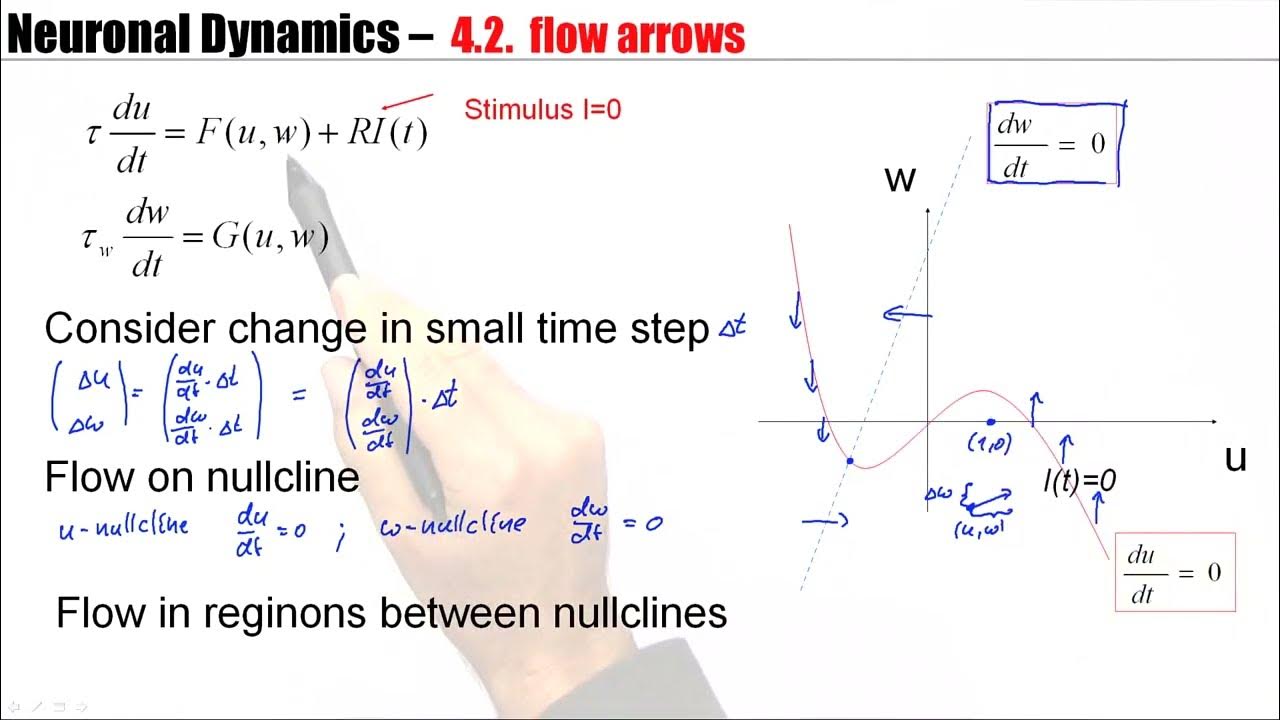
![CNS4.2 - Phase Plane Analysis - YouTube](https://i.ytimg.com/vi/_63Y2qiUqbI/maxresdefault.jpg?sqp=-oaymwEmCIAKENAF8quKqQMa8AEB-AH-CYAC0AWKAgwIABABGFsgWyhlMA8=&rs=AOn4CLDQ1o8sFzmOp1CqSi70K6G9eJdzrg)
![Solved The phase diagram shown is for C_2CI_4 a substand | Chegg.com](https://i2.wp.com/d2vlcm61l7u1fs.cloudfront.net/media/4f9/4f98bc84-92f6-47d6-84a8-084005875572/phpG9UpQF.png)
![Figure C.2: Phase Diagram: ξ 0 = 0.98 × ξ L and ξ 1 > ξ L | Download](https://i2.wp.com/www.researchgate.net/publication/338614906/figure/fig9/AS:893098741735426@1589942741473/Figure-C2-Phase-Diagram-x-0-098-x-L-and-x-1-x-L.png)
![Perspective view of phase 2-LT phase along the c (top) and the b](https://i2.wp.com/www.researchgate.net/publication/348915610/figure/fig1/AS:987091987095553@1612352477986/Perspective-view-of-phase-2-LT-phase-along-the-c-top-and-the-b-bottom-axes.png)
![2 Phase diagram of C 2 H 6 − CO 2 in the T − p plane. C 1 is the](https://i2.wp.com/www.researchgate.net/profile/Zhan-Chao-Hu/publication/357766113/figure/fig1/AS:11431281086513584@1664247348430/Phase-diagram-of-C-2-H-6-CO-2-in-the-T-p-plane-C-1-is-the-critical-point-of-C-2-H-6.png)